A. Calculation Method
The circuit calculation method is associated with a circuit type/subtype and is specified in the parts input system within the Amend Circuit Types and Subtypes menu.
The circuit calculation method defines the type of calculations that are performed for a specific circuit type/subtype. For example, “Initiating/Alarm” circuits check voltage drop calcs using supervisory values, whereas “Notification/Audio” circuits check for dB loss. The currently defined methods are:
• NONE: Indicates that this circuit is not calculated, however the allowable maximum number of devices is used. Any number of appliances may be connected to this circuit up to the allowable maximum.
• Supervisory: The standard voltage drop and total circuit draw checks are performed for this circuit. Supervisory current values are used for all devices. This would be the standard method for initiating circuits. Wire Capacitance Check is made.
• SLC: Currently, this is the same as Supervisory. Future unique enhancements may be made.
• Alarm: The standard voltage drop and total circuit draw checks are performed for this circuit. Alarm current values are used for all devices. This would be the standard method for notification circuits. Wire Capacitance Check is made.
• dB Loss: dB Loss is calculated for appliances on this circuit. This would be the standard method for Speaker circuits.
• Strobe: Similar to Alarm method, however the appliance current draw is based on a specific calculation as outlined below.
• Addressable Notification: Specific calculations for addressable notification circuits are performed, as outlined below.
Additional calculation methods may be added via the parts input system under the Define Calculation Method menu. The actual calculation procedure will have to be submitted to SEI for coding.
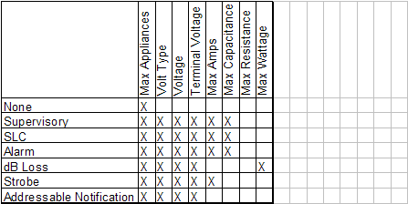
Specific circuit information is entered on the Circuit Data menu in the parts input system. Not all information in this table is used for each calculation method. The table below shows circuit information that is selectively used by the calculation methods:

See Calculation Method Descriptions below, for complete information.
B. Calculation Length Mode
Calculations are based on one of two length modes:
• Running (or Point to Point): – uses the actual length to each appliance.
• Lump Sum: calculates all devices at the maximum length.
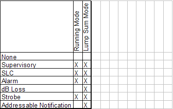
This is a general system wide user setting on the Design_Standards/Calculations settings menu. Note that some calculation methods only run in Lump Sum Mode. The table below shows what length mode each calculation method will run in:

When Running Length Mode is selected, dB Loss and Addressable Notification methods will automatically switch to Lump Sum Mode.
C. Calculation Method Descriptions
Supervisory Method:
SLC Method:
Alarm Method:
Terminal Voltage
Calculations begin at the source with the listed terminal voltage and proceed toward the remote device on the circuit. A 24V circuit will typically have a terminal voltage listed at 20.4V. If the terminal voltage is not supplied, then the full circuit voltage value will be used as the terminal voltage.
Circuit Calculations
These methods differ in their use of current values. Supervisory and SLC use Supervisory Current associated with an appliance, Alarm uses the Alarm Current. The following checks are made in both methods:
• Voltage Drop Check
Using OHMS LAW (V=IR)
Voltage Drop is calculated for each segment beginning at source working toward remote appliance.
CurrentDraw = Summation of current draw of all downstream appliances
WireResistanceDrop = DBValue for cable (resistance/foot)
Length = wirelength*2 (two conductor cable)
Resistance = Length*WireResistanceDrop
Vdrop = Resistance*CurrentDraw
The appliance must be operating above the minimum operating voltage, or an error message will be generated. The minimum operating voltage is determined by either the minimum voltage specified on the appliance circuit, or the circuit maximum voltagedrop. [The circuit maximum voltagedrop is determined by the system wide volage drop percentage (default 10%) times the terminal voltage. (Typically 20.4X10% = 2.04 circuit maximum voltage drop.]
If minimum app voltage is not set, the circuit maximum voltagedrop is used.
If minimum app voltage is set, the higher of the two values is used.
• Current Check
Compare total current draw against rated value for circuit
Error if (m_dTotAmp > pCircuit->m_rMaxAmps)
dTotAmp = Summation of all operating amperages of all appliances on circuit
pCircuit->m_rMaxAmps = DBValue for circuit
• Wire Capacitance Check
A check is made to insure that the total cable length of the circuit is under the maximum cable length allowed based on the maximum cumulative capacitance for the circuit.
Maximum Cumulative Capacitance
This value is specified in microfarads and is figured as follows:
1. Using the max capacitance specified for a circuit:
If the maximum capacitance value is specified on a circuit, then this value is used. This optional field may be specified by the user on the circuit data tab via the parts input system. If this value is unspecified or 0, then we proceed to the next step:
2. Using the baud rate specified for a circuit:
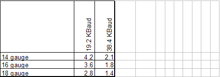
A baud rate may be specified for a circuit. This optional field may be specified by the user on the circuit data tab via the parts input system. If this baud rate is specified, then we use the built in capacitance table to obtain the Maximum cumulative capacitance, which is based on wire gauge size and baud rate:

If the value cannot be obtained from this table, then we proceed to the next step:
3. Using the default value of .5 microfarads:
If neither of the above two values were specified, then the system will use a default value of .5 microfarads.
Maximum Cable Length Determination (Wire Capacitance Check)
The maximum cable length is equal to the maximum cumulative capacitance divided by the capacitance per foot:
ML Maximum Cable Length
MCC Maximum cumulative capacitance measured in microfarads (10^-6)
CPF Capacitance per foot measured in picofarads (10^-12))
This value is associated with the cable in the database.
ML = MCC/CPF
Example:
MCC = .5 microfarads
CPF = 30 picofarads (from database based on cable size)
ML = .5 microfarads / 30 picofarads
= 500,000 / 30
= 16,667 Feet maximum total length
Strobe Method:
Terminal Voltage
Same as Alarm method above
Circuit Calculations
Similar to Alarm method above, however the appliance current draw is based on a specific calculation based on the following formula:
SpecCurrent = AlarmCurrent+([(AlarmCurrent-CalcCurrent)/(Voltage-MinVoltage)]*(Specvoltage-Voltage))
The individual data in involved are:
Voltage From tblApplReqdCirc
MinVoltage From tblApplReqdCirc
SpecVoltage System value set in Design Standards/Calculation page
AlarmCurrent From tblApplReqdCirc
CalcCurrent From tblApplReqdCirc
-An example of this calculation is:
Given Data:
Voltage 24 V
MinVoltage 17V
SpecVoltage 18V
AlarmCurrent .08 A (80 mA )
CalcCurrent .12A (120 mA )
SpecCurrent = .08 + ( [ (.08-.12A) / (24 - 17) ] * (18-24) )
SpecCurrent = .08 + ( [ (-.04) / 7 ] * (-6))
SpecCurrent = .08 + ( [ -.00571 ] * (-6))
SpecCurrent = .08 + .0342
SpecCurrent = . 1142
Therefore a strobe with a rated AlarmCurrent of .08 A (80mA) will actually use a current of .1142 ( 114. mA), based on the above data. This applies to both circuit and Battery Calculations
Note the if CalcCurrent, MinVoltage, or SpecVoltage are zero, the AlarmCurrent
Value will be used as the SpecCurrent.
System Checks
The following checks are made, see section above for details:
• Voltage Drop Check
• Current Check
dB Loss Method:
Terminal Voltage
Same as Alarm method above
Circuit Calculations
Note that these calculations are always based on lump sum length mode (all devices placed at maximum length). The setting available from the Design_Standards/Calculations settings menu will be ignored.
• DB Loss Check
DB loss is checked for a maximum of a –3dB drop.
Total Circuit Load (Watts)
P = Total Circuit Load Summation of rated wattage taps of circuit speakers
Total DB Loss
E = Circuit Voltage Typically 25v
Iwf = Wire Ohms/foot based on partsdb wire gauge (ie #16 may= .0041/ft)
L = Total circuit length
I = Current P/E
R = Resistance E/I
Rc = Circuit Resistance L*2*Iwf
Rt = Total Resistance Rc+R
Es = Voltage @ Speaker (E*R)/Rt
Ps = Wattage @ Speaker (Es)^2/R
Db = Total DB Loss log(Ps/P)*10
• Maximum circuit length check
Allowable maximum circuit length is calculated and checked against actual length.
We use the general formula below to determine max length, that can accommodate any max db drop:
Max Circuit Length Dm
Dm = (( (E*R) / ((P*R*Z)^.5) ) - R) / (2.*Iwf);
Where same values apply as above with the addition of:
Z = 10^(DB/10.)
DB = max db drop allowed (typically –3dB)
Note the more common formula for a specific –3dB drop:
Dm = (E^2*.293)/(P*Iwf*.707)/2
Note: Formula specific for a –3dB drop
These formulas are identical for the case of –3dB max drop.
• Max Wattage Check
Insure that the required wattage is operating under the allowable wattage limit. The allowable wattage limit is determined by taking the listed max wattage for the circuit and multiplying it by the system wide Wattage load factor. Example: Assume listed max wattage is 50W, and the maximum wattage load factor is 80%. The required wattage would have to be operating under 50W*80% = 40W. Note that only a warning message will be generated when this check fails, the circuit will be calculated anyway.
Addressable Notification Method:
This method will force lump sum mode calculations. The appliance current value will be taken from the Alarm Current Value as listed on the appliance circuit. This method will work with or without circuit branching. The following checks are made:
• Voltage Drop Check
• Current Check
Note that these checks are identical to the same checks as listed above under the Supervisory and Alarm Methods.
In Addition, the Maximum Allowable Distance to Furthest Device value is calculated based on the following formula:
is_cnt = total number of isolators per circuit (or branch if applicable)
iwf = Wire Ohms/foot based on partsdb wire gauge (ie #16 may= .0041/ft)
max_amps = total amperage load of circuit (or branch when applicable)
MaximumAllowableDistance = 10 + ((2 - .1*is_cnt) /2) - (25*iwf)) / (max_amps*iwf))
Additional Notes:
Use Of Supervisory and Alarm Current Values
Supervisory and Alarm current associations:
1. Appliance circuits Supervisory and Alarm values are associated with each circuit listed on each appliance (panels, modules included).
2. Base Appliance circuits Supervisory and Alarm values are associated with each circuit listed on each base.
3. Base Supervisory and Alarm values specified once per base.
4. Panel modules Supervisory and Alarm values specified once per panel module.
Current Evaluation for circuit calculations:
ALARM Calculation Method use the Alarm Current Values. The SUPERVISORY and SLC Calculation Methods use the Supervisory Current Values.
When an appliance is placed in the drawing, its circuit list will combine all circuits from its base and appliance circuit lists (1 and 2 above).
Its base circuits are listed first.
The primary circuit is considered to be the first circuit that appears on the list.
The Base Supervisory and Alarm values (3 above) are used as additional values to be added only to the primary circuit of the appliance.
Value 4 above is not used in circuit calculations. It is used in battery calculations only.
Use of Branch Count
Note that circuits using “branch count” will also always be calculated in lump sum mode. See the paper on Branched Circuits for details.