![]()
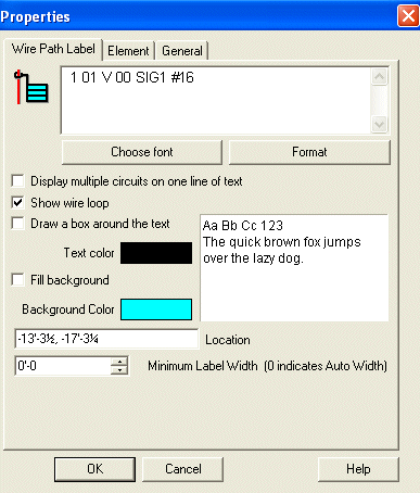 The Wire
Path Label tool equips the cursor to place a tag bearing relevant
location and assignment information anywhere along a stretch of cable.
The Wire
Path Label tool equips the cursor to place a tag bearing relevant
location and assignment information anywhere along a stretch of cable.
Text and background colors can be edited as needed by clicking the corresponding color palette boxes. The Location field shows the label's physical coordinate location in the drawing. The last editable field displays the label's width, and defaults to zero, which indicates Auto Width.
The first dialog box indicates the Wire Path's corresponding circuit and device address.
Its font and address formatting can be changed with either button. To be routed directly to information about the Format Button, click here.
Display multiple circuits on one line of text allows all circuits in a wire path to display within one line, with a comma separating them.
Selecting the Show wire loop option places a loop at the end of the leader line, and around the corresponding wire path. The loop can be left out of the label, since it may obscure shorter wire paths.
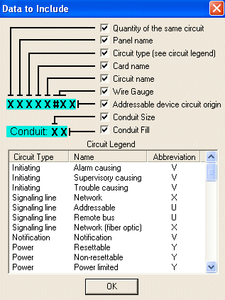 The Data
to Include dialog is a legend explaining the wire path label information.
The Data
to Include dialog is a legend explaining the wire path label information.
Check or un-check the boxes to include or exclude information from wire path labels, such as panel name, circuit type, conduit size, etc.
The bottom Circuit Legend sorts the Circuit Types, Names, and Abbreviations used in the application.
Place Wire Path Labels Command
![]()