![]()
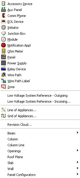
The AlarmCAD for AutoCAD Tools menu and its submenus allow access to the following functions and settings:

Accessory Device: Equips the cursor to place an accessory device in the drawing.
Aux Panel: Equips the cursor to place an Auxiliary Panel in the drawing.
Comm Phone: Equips the cursor to place a communications telephone in the drawing.
EOL Device: Equips the cursor to place an end-of-line resistor in the drawing.
Initiator: Equips the cursor to place an initiator (i.e. smoke detector, heat sensor or manually activated alarm) in the drawing.
Junction Box: Equips the cursor to place a junction box in the drawing.
Module: Equips the cursor to place a module (i.e. contact monitor, detector monitor or line isolator) in the drawing.
Notification Appliance: Equips the cursor to place a notification appliance (i.e. bell, strobe, horn or chime) in the drawing.
Ohm Meter: Equips the cursor to place a measuring device on any appliance in the drawing.
Panel: Equips the cursor to place a main or local panel in the drawing.
Power Supply: Equips the cursor to place an energy source in the drawing field.
Relay Device: Equips the cursor to place a door holder into the drawing field.
Wire Path: Equips the cursor to connect panels and appliances.
Wire Path Label: Equips the cursor to place a label with relevant location and assignment information anywhere along a stretch of cable.
Zone: Equips cursor with a boundary tool that creates area designations for control panel programming. (Zone association appears on Appliance Lists.)
Low Voltage System Ref (Outgoing): Equips the cursor to place an outgoing low voltage system reference in the drawing.
Low Voltage System Ref (Incoming): Equips the cursor to place an incoming low voltage system reference in the drawing.
Line of Appliances: Opens the Line of Appliances dialog to specify parameters for laying out a basic line of connected initiators, notifiers or modules, then equips the cursor with a line tool to designate where to lay out the line of appliances.
Grid of Appliances: Opens the Grid of Appliances dialog to specify parameters for laying out a basic grid of connected initiators, notifiers or modules, then equips the cursor with a boundary tool to designate the area in which to lay out the grid.
Revision Cloud: Opens the Revision Cloud Properties dialog to specify chord length, and text information, including font type, then equips the cursor the draw a revision cloud.
Beam: This submenu has options for types of beams with which to equip the cursor.
Column: Equips the cursor to place a column in the drawing.
Column Line: Equips the cursor to place a column line in the drawing.
Openings: This submenu has options for types of openings to create in a beam or wall element in the drawing.
Roof Plane: Equips the cursor to establish a roof plane section in the drawing.
Slab: Equips the cursor to place a slab in the drawing, either from its end locations or corner and edge location.
Wall: This submenu has options for types of walls with which to equip the cursor.
Panel Configurators: This submenu has an XLS Panel Configuration option which opens the Siemens XLS Configuration dialog.