![]()
 Clicking the Initiator
icon from the Alarm Tools toolbar
or item from the Tools menu equips
the cursor to place a smoke detector, heat sensor or manually activated
alarm device into the drawing field.
Clicking the Initiator
icon from the Alarm Tools toolbar
or item from the Tools menu equips
the cursor to place a smoke detector, heat sensor or manually activated
alarm device into the drawing field.
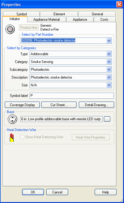
To access the Initiator's Properties Page, double-click its symbol in the drawing. Alternatively, right-click the symbol and choose Properties from the pop-up menu.
Select initiators by their part numbers in the top drop-down menu. Notice how the Part Number corresponds to the selections in the remaining drop-down menus. Filtering the Type, Category, Subcategory, and Description variables in the Select by Categories section can help locate the part as well.
Customize the Symbol Label in the editable field below the Select by Categories section.
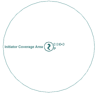 Coverage Display
Modify the coverage display through the main Properties Page. The left image illustrates an initiator's coverage display. Click here to learn more about the Coverage Display dialog.
Click the Cut Sheet button to open an Adobe Reader .pdf file with the manufacturer's specs.
Click the Detail Drawing button to assign manufacturers' detail drawing to the device, if applicable.
![]() For initiators that require a base, the Appliance Base dialog is accessed
via the browse button located to the right of the initiator's default
base.
For initiators that require a base, the Appliance Base dialog is accessed
via the browse button located to the right of the initiator's default
base.
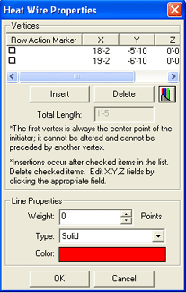 For initiators that require Heat Detection Wire, click
the Heat Wire Properties button
to open its Properties page, shown at left.
For initiators that require Heat Detection Wire, click
the Heat Wire Properties button
to open its Properties page, shown at left.
Alter the wire's path by Inserting or Deleting vertices listed in the window, and click the cable icon to access the Cable Properties page.
In the Line Properties dialog box at the bottom, display settings are assigned for the heat wire. Line weight (in points), type (such as solid, dash, dot, etc.) and color are adjusted here as well.
On the Appliance Material tab, assign material and trim kits to the device to be picked up during listing.
The Appliance tab presents Connection Data, Requirements and Circuit load in addition to Network Circuit Data.
The Costs tab allows users to assign the cost-per-item and labor costs to be used in stock listing and other reports.
Refine the on-screen presentation of the device's appearance, location, rotation and scale on the Symbol tab.
The Element tab displays the Unique ID number and lists other elements to which it is joined.
On the General tab, change the device's color, layer, line properties and rendered characteristics.
Parts Database: Add New Appliance Base
![]()