![]()
Access: Using the mouse, right-click in any area where toolbars can be docked and click AlarmCAD: AlarmCAD Tools
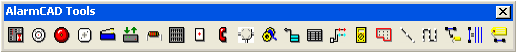
The AlarmCAD for AutoCAD AlarmCAD Tools toolbar has buttons to equip the cursor with a wide array of drawing tools, which are used to create various alarm component elements. Selection of certain tools opens dialog boxes for setting of parameters for the element to be placed, then equips the cursor with the tool.
All elements created using these commands have the current default properties for that element, which are accessed using the Default Properties submenu of the View menu (or can be changed using the Product Line toolbar). Once you have drawn an element, you can change away from the default properties if desired by accessing the element's Properties dialog box.
Available options on this toolbar include the following:
![]() Panel:
Equips cursor with the panel tool. Places a main or local panel in the
drawing.
Panel:
Equips cursor with the panel tool. Places a main or local panel in the
drawing.
![]() Initiator:
Equips cursor with the initiator tool. Places a smoke detector, heat sensor,
or manually activated alarm element in the drawing.
Initiator:
Equips cursor with the initiator tool. Places a smoke detector, heat sensor,
or manually activated alarm element in the drawing.
![]() Notification Appliance:
Equips cursor with the notifier tool. Places a bell, strobe, horn, or
chime in the drawing.
Notification Appliance:
Equips cursor with the notifier tool. Places a bell, strobe, horn, or
chime in the drawing.
![]() Module:
Equips cursor with the module tool. Places a contact monitor, detector
monitor, or line isolator in the drawing.
Module:
Equips cursor with the module tool. Places a contact monitor, detector
monitor, or line isolator in the drawing.
![]() Relay Device:
Equips cursor with the relay device tool. Places a door holder in the
drawing.
Relay Device:
Equips cursor with the relay device tool. Places a door holder in the
drawing.
![]() Aux Panel:
Equips cursor with the Auxiliary Panel tool to be placed in the drawing.
Aux Panel:
Equips cursor with the Auxiliary Panel tool to be placed in the drawing.
![]() EOL Device:
Equips cursor with the EOL device tool. Places an end-of-line resistor
in the drawing.
EOL Device:
Equips cursor with the EOL device tool. Places an end-of-line resistor
in the drawing.
![]() Power Supply:
Equips cursor with the power supply tool. Places a power supply in the
drawing.
Power Supply:
Equips cursor with the power supply tool. Places a power supply in the
drawing.
![]() Accessory Device:
Equips cursor with the accessory tool. Places an accessory device in the
drawing.
Accessory Device:
Equips cursor with the accessory tool. Places an accessory device in the
drawing.
![]() Comm Phone:
Equips cursor with the phone tool. Places a communications telephone in
the drawing.
Comm Phone:
Equips cursor with the phone tool. Places a communications telephone in
the drawing.
![]() Junction
Box: Equips cursor with the junction box tool. Places a junction
box in the drawing.
Junction
Box: Equips cursor with the junction box tool. Places a junction
box in the drawing.
![]() Wire Path:
Equips cursor with a special line tool. Draws cable to connect panels
and appliances, or creates wire paths.
Wire Path:
Equips cursor with a special line tool. Draws cable to connect panels
and appliances, or creates wire paths.
![]() Wire Path Label:
Equips cursor with the label tool. Places a tag with relevant location
and assignment information on a stretch of cable.
Wire Path Label:
Equips cursor with the label tool. Places a tag with relevant location
and assignment information on a stretch of cable.
![]() Reports:
Opens a dialog box for selection of a report, then (after desired entries
are made in the dialog box for the selected report) equips the cursor
to place the report in the drawing.
Reports:
Opens a dialog box for selection of a report, then (after desired entries
are made in the dialog box for the selected report) equips the cursor
to place the report in the drawing.
![]() Riser Detail:
Opens a new window for riser detail.
Riser Detail:
Opens a new window for riser detail.
![]() Ohm Meter:
Equips cursor with the ohm meter tool. Places a measuring device on any
appliance in the drawing.
Ohm Meter:
Equips cursor with the ohm meter tool. Places a measuring device on any
appliance in the drawing.
![]() Zone: Equips
cursor with a boundary tool to denote an area (also known as a software
zone) for control panel programming. Zone association appears on appliance
lists.
Zone: Equips
cursor with a boundary tool to denote an area (also known as a software
zone) for control panel programming. Zone association appears on appliance
lists.
![]() Line of Appliances:
Equips cursor with a special line tool. Allows user to quickly place a
series of connected initiators, notification appliances, or modules along
one line.
Line of Appliances:
Equips cursor with a special line tool. Allows user to quickly place a
series of connected initiators, notification appliances, or modules along
one line.
![]() Grid of Appliances:
Equips cursor with a boundary tool. Allows user to quickly place a series
of connected initiators, notification appliances, or modules, connected
and laid out in a grid.
Grid of Appliances:
Equips cursor with a boundary tool. Allows user to quickly place a series
of connected initiators, notification appliances, or modules, connected
and laid out in a grid.
![]() Get
Default From Selection: Allows user to quickly change the default
properties of an element or group of elements.
Get
Default From Selection: Allows user to quickly change the default
properties of an element or group of elements.
![]() Select All Like
Selected: Allows user to quickly
select all elements in the drawing that are of the same type as
the currently selected element.
Select All Like
Selected: Allows user to quickly
select all elements in the drawing that are of the same type as
the currently selected element.
![]() Properties:
Brings up the Properties
page for any selected element and displays
various characteristics unique to that element.
Properties:
Brings up the Properties
page for any selected element and displays
various characteristics unique to that element.
![]()