 The Riser
Detail reporting tool creates a more compact and organized schematic
(rather than diagrammatic) presentation of a drawing. Riser Details help
simplify and unclutter the most complex drawings, so installers, inspectors,
and other personnel can determine where appliances connect, how many circuits
connect to each appliance, etc. To generate a schematic view for a drawing,
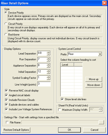
choose Riser Detail from the Reports menu. Since the Riser
Detail Options dialog contains several Style, Display, and Settings
options, each is described more in detail below.
Device Priority: Each device in the drawing will appear once in the Riser Detail. Primary circuits display as the main circuit, and secondary circuits display as subordinate circuits to the primary.
Circuit Priority: Every active circuit displays separately. Each device will appear on all of its primary and secondary circuit displays.
Backbone: Using Circuit Priority, each Panel is shown, but not each individual device. Every circuit branch is displayed along with its device count only.
Click here to view sample Riser Detail Reports that represent each style option.
 Display Options include several fields and options to
maximize the Riser Detail display.
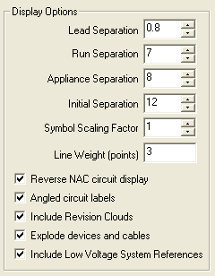
Please Note: Separation values are shown in units originally defined in the Settings/Format menu. The image on the left shows the default values, but users can modify each field.
Lead Separation defines the distance that circuits will lead off from the Panel's bottom side.
Run Separation defines how far apart circuits are spaced from each another.
Appliance Separation dictates how far apart appliances are spaced in a circuit.
Initial Separation defines the distance from the source to the first appliance.
Symbol Scaling Factor dictates the size of symbols compared to text.
Line Weight displays in points.
Reverse NAC circuit display will show the devices toward the left of the Panel in descending order. Leaving the option unchecked causes the attached devices to display to the right of the Panel in descending order.

 Selecting
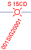
the Angled circuit labels option
causes the address labels to display below the appliance at a 60
The image on the right illustrates the option as disabled. To avoid interference with circuit paths, the appliance's circuit label appears above the symbol, as does the Strobe's candela rating.
Include Revision Clouds: If the AlarmCAD for AutoCAD drawing has revision clouds, to include or exclude them from Riser Details reports. For additional information on revision clouds, click here.
Explode devices and cables: Causes the device to split into separate symbol entities (i.e. In the Riser Detail report, when users double-click the device, the symbol's properties appears, not the device's actual properties.
Include Low Voltage System References: If the AlarmCAD for AutoCAD drawing contains Low Voltage System References, check this option to include them in the Riser Detail.
.gif) Divide areas, floors, levels,
etc. in a multi-level building by adjusting the System Level Control.
Adjusting the System Level Control can tidy up the Riser Detail Report
and can help those who have to work from the reports.
Divide areas, floors, levels,
etc. in a multi-level building by adjusting the System Level Control.
Adjusting the System Level Control can tidy up the Riser Detail Report
and can help those who have to work from the reports.
The first Prefix field provides a drop down menu to help define the different areas of the alarm system. Customize this field if the choices do not quite describe the appliance's positioning in the system. Please remember that each device's Appliance Page dictates the System Level ID, and thus the available Levels in the list dialog.
Move Up/Move Down buttons: Position the Levels in ascending, descending, or mixed order. Highlight the row first, then hit the Move Up or Move Down button to reposition the level.
Show level site lines: This option is turned on by default, but can be turned off. The image above left illustrates level site lines. A customized Prefix will only display when this option is turned on.
![]() The Maximum Display Width
option is disabled by default, but a user-specified maximum width will
cause any circuits that extend beyond the maximum length to wrap around
the sheet back to the center, so all the devices will fit on one sheet.
The Maximum Display Width
option is disabled by default, but a user-specified maximum width will
cause any circuits that extend beyond the maximum length to wrap around
the sheet back to the center, so all the devices will fit on one sheet.
 At the bottom of the Riser
Detail options dialog is the option to choose a default settings (.cas) file to use in a Riser Detail
Report. The browse button on the right enables the search for a .cas file. After the file is loaded
(after the OK button is pressed), all parameters for text size, appliance
size, etc. will be reset to the settings of the .cas
file.
Changes made to the Riser Detail schematic will not appear in the original drawing and vice-versa. If items need to be permanently added or removed, edit the original AlarmCAD for AutoCAD drawing and generate another Riser Detail.
Systems containing circuit connections between multiple sources display each source separately, one on top of the other, in the Riser Detail report.
To reset the default options, simply click the Restore Default Options button on the bottom left of the Riser Detail dialog.
After modifying the Riser Detail Options dialog, click OK to run the Riser Detail report.
Default options are helpful to first-time users who have not already run a Riser Detail Report.