|
|
|
AutoSPRINK Training Site - Microsoft Windows Basics (AutoSPRINK)
|
|
The AutoSPRINK CAD system is constructed around The Windows operating systems. To
be proficient with the AutoSPRINK system, you must first understand some basic facts
about the use of Windows controls. Before you begin to design and draw using the
AutoSPRINK CAD system, review the information below or use other sources to gain
a working knowledge of Windows basics.
Menus
The Menu Bar
Across the top of the AutoSPRINK screen, a row of menu selections point
the way to various tasks necessary for design. To display a menu for the purpose
of making a selection, click on its title in the menu bar (or press AL T, followed
by the underlined letter in the menu name). I.e. the File menu can be accessed by
pressing AIt-F on your keyboard.
Menu Entries
A menu displays entries grouped according to the types of operations
they perform. There are several ways in which you can choose a menu entry that performs
an action or displays a dialog box. With practice, shortcuts can lead to greater
speed.
If the menu is currently displayed, you can click on an entry with the mouse or
use the arrow keys to choose entries sequentially (then press ENTER to execute),
click on an entry, or simply press the key that corresponds to the underlined character
in the entry. If the entry displays a submenu, you can then use any of the techniques
mentioned above to choose entries in the submenu. As with menus, you can press the
ESCAPE key to exit.
|
|
|
|
|
|
Dimmed Menu Items - When a menu title is dimmed, that selection
is currently unavailable due to conditions at the time the menu is viewed.
|
|
|
|
|
|
|
Active Menu Items - Available as a choice to the operator (not dimmed when the menu
is viewed). Please note that this choice indicates that a keyboard equivalent exists
(F3) which enables you to choose a menu entry from the keyboard without actually
using the menu. Also, pressing the ALT, followed by the underlined letter in the
menu name, followed by the underlined letter in the menu entry provides a shortcut
for the command.
|
|
Submenu - A submenu is indicated by an arrow, located at the right
of the menu item. A list of entries related to the menu item will be displayed.
Choosing a submenu entry will either perform an action or open a dialog
|
|
|
|
|
|
|
Checked Menu Item - A check mark to the left of a menu item, (not shown) indicates
that an attribute is applied or a function is in effect. You may uncheck the item
using the cursor if you wish to reverse the effect.
|
|
Directory Dialog Boxes for Opening Files
Opening files is very straight forward using the Windows convention. To help remember
the location of a file saved long ago, use the Windows FIND facility of the Start
Menu prior to selecting the Open Dialog Box. To open a drawing file (.cad) in AutoSPRINK,
simply choose 'Open' in the File Menu and select desired file.
Scroll List
Displays the contents of the open drive and directory. Use the scroll box/arrows
to scroll through the list. To select a file, click on Its name or scroll with the
up/ down keys. To speed the process, double dick on a file name to open it.
|
Directory/Folder Title
Displays the name of the selected folder. To display the contents of the
other drives and folders, choose from the tree structure of the drop-down list.
If you want to open a file from a floppy disk, insert the disk containing the desired
file, and select the A drive.
|
File Name
Enter the name of a document and click OK by selecting it from the scroll list.
If the document is not contained In the current directory, you may specify the path
to the document.
|
|
File Type Filter
File with the .cad (AutoSPRINK) extension or .cap (AutoSPRINK Plot Sheet) will appear
in the selection list with this setting. To View another file type, use the dropdown
list and change the setting. Users will need to select 'All Files' to see older
.mdr files
|
|
Open File
To open a file, select its name in the list and click open or double click on its
name.
|
|
|
|
Toolbars
Ease of use is stressed throughout the AutoSPRINK system and the easiest way to
invoke Windows commands is through the use of icons (tools). Icons created by M.E.P.
CAD, containing small 'pictures' for more clarity, are used as shortcuts for commands
that occur fairly often. Icons are sometimes grouped together when they invoke related
commands. These groups are called TOOLBARS. Toolbars can be moved around the screen
for convenience and space considerations. They can also be turned on and off (made
visible) as desired by use of the View sub-menu. Toolbars are activated (visible)
under the View Menu. Tool Tips are available by lingering over a button with the
cursor. The command tip appears and move descriptive text is displayed on the status
bar. Use the cursor to move Toolbars around the screen or “docked" to certain locations
on the screen and to each other in some cases.
|
|
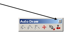
Exit Button - Click the X or exit button to dear Toolbars from the screen. To bring
Toolbars back up to the screen, select the Toolbars choice from the view menu and
select Toolbar of choice from the list.
|
|
|
A dialog box is displayed on-screen after choosing a menu command followed by an
ellipsis or from pressing a button on the screen. A dialog box contains fields and
controls that enable you to make a number of settings. Pressing the TAB key highlights
the next control; pressing SHIFT TAB highlights the previous control.
The units entered into fields will depend on what units have been set under the
Number Format Settings available from the Settings Menu, Format selection. In the
Text Input Window, you can enter mixed values as long as you specify measurement
units that differ from the Number Format Settings. When a button is surrounded by
a thick border, pressing the ENTER key will perform the same operation as clicking
the button.
|
|
|
|
|
Tabs - Tabs represent files or folders containing information or functions. Click to activate.
|
|
Drop-down List Indicator - A drop-down list is a space saving method of providing several options. Click on the arrow to display the list of options to choose from.
|
|
|
|
|
Field -
Enables you to enter specific values in either alpha or numeric.
|
|
Check box
represent three options for activation, deactivation or not available. They are selected with the cursor ( or by tapping the space bar when the Ctrl is active). A checked box indicates that an option is active. A grayed stale suggests the user should not change current setting.
|
|
|
|
Button - Clicking a button does one of three things:
• performs a task
• selects an option
• opens or closes a dialog box
|
|
|
|
|
Drop-down Lists - like a menu within a dialog box. Clicking the arrow on the right side displays the drop-down list.
These drop-down lists enable you to choose a value from the menu, or if the drop- down list includes a field, you may enter a value into that field. To display the drop-down list, cl ick on the arrow to the right of the field.
|
|
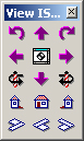
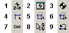
View ISO Rotator Tools
|
Precise viewing options will require that you make the View ISO Rotator Tools visible,
by activating Toolbars in the View menu and selecting View ISO Rotator. The View
ISO Rotator Tools are designed for ultimate viewing options; allowing users to rotate
drawings to specific placement and zoom level and providing more accurate view settings
for superior design and placement capabilities. The View ISO Rotator Tools can be
located anywhere in the AutoSPRINK environment or docked in the gray housing areas
located around the main drawing screen. The various functions associated with the
View ISO Rotator Tools are listed and defined below.
|
1. Roll View Left Has the effect of Rotating the camera's perspective
of the drawing counter-clockwise as the viewer would observe It.
2. Yaw View Left Has the effect of Rotating the camera's perspective
of the drawing left as the viewer would observe it.
3. Rotate View left Has the effect of Rotating the drawing to the
left around the Z-axis as the viewer would observe it.
4. Left Side View Rotates the drawing so as to show the left side
in elevation.
5. Isometric NE View Rotates the drawing into an isometric northeast
view, for continued design or allow user a quick 3D look at the drawing
6. Pitch View Up Changes the view to where the camera (observer)
tilts up In small Intervals In relation to the drawing.
|
7. Benchmark View Assigns the view settings with the Benchmark
acting as a pivot point. Changing the view after this selection will rotate the
drawing around the Benchmark pivot while keeping the Benchmark at the center of
the screen
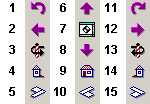
8. Pitch View Down Changes the view to where the camera (observer)
tilts down in small intervals in relation to the drawing.
9. Front View Changes the view to a front elevation with the camera
(observer) straight in front of the drawing.
|
10. Isometric NW View Rotates the drawing into an isometric northwest
view, for continued design or allow user a quick 3D look at the drawing
11. Roll View Right Has the effect of rotating the camera's perspective
of the drawing clockwise as the viewer would observe it.
12. Yaw View Right Has the effect of rotating the camera's perspective
to the right as the viewer would observe it.
13. Rotate View Right Has the effect of Rotating the drawing to
the right around the Z-axis as the viewer would observe it.
14. Right Side View Rotates the drawing so as to show the right
side in elevation
15. Isometric SE View Rotates the drawing into an isometric southeast
view, for continued design or allow user a quick 3D look at the drawing
|
|
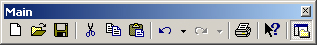
Main Toolbar
The Main Toolbar contains tools for basic windows operations such as opening files, saving files to hard and transportable disks, cut, copy and paste operations, as well as undo/redo and the print command.
Using cut, copy, and paste operations in AutoSPRINK follows the same procedures used in all Windows applications. These operations allow for quick movement, duplication and deletion of elements to and from locations within the same drawing, between separate drawings or to the 'Parts Tree.' The Main Toolbar also contains a special context sensitive help button whereby the user can select specific areas of the screen, such as Toolbars, snaps or viewing functions, for access to information regarding use and operation. This help button is located to the far right of the Main Toolbar and is distinguished by a question mark and arrow icon. You also have the option to show or hide the ‘Parts Tree’ window.
|
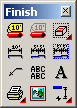
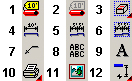
Finish Toolbar
|
The Finish toolbar has buttons for various commands used to clean up or help complete a drawing that is nearly finished.
|
|
|
1. Update Pipe Labels - The Update Pipe Labels Tool provides access to the pipe label properties of all pipes in a drawing. Users can activate, remove or modify labels with one tool.
2. Toggle Pipe Labels Display - Toggles visibility of all pipe labels current to a drawing. Labels can be set to visible or non-visible using this tool, providing for better control and accuracy during the design process.
3. View Element Tool - Enables the user to drag a view rectangle and selects any valid .cad drawing or detail for placement inside. Drawings or details can be scaled to fit view rectangle.
4. Point-to-Point Dimension - Equips cursor with the dimension tool. Used to indicate the distance between any two points you specify; draws a dimension indicator with the distance between the points.
5. Running Dimension - Equips cursor with the dimension tool. Used to Indicate the distance between each pair of points you specify along a line; draws dimension indicators with the distance between each pair of points.
|
6. Dimension an Area - Equips cursor with a boundary tool to denote an area for dimensioning, then draws dimension indicators with the distance between locations in the defined area.
7. Leader line Tool - Enables user to place polylines with attached arrows.
8. Text Box Tool - Enables user to add text to a drawing by placing a text box and applying text within.
9. Text line Tool - Enables user to add text to a drawing by placing a text line and applying text along the line.
10. Print - This extension fly-out extends to display the tools on the Print toolbar.
11. Picture - Allows the user to take a bitmap image from an external file and insert it into the drawing field.
12. Star Dimensions - This extension fly-out extends to display the tools on the Star Dimensions toolbar.
|
|
Pipe Toolbar

|
The AutoSPRINK Pipe toolbar in the Simple Interface allows users to select default properties for pipes added to a drawing. There are a few differences from the Pipe Properties toolbar in the Standard Interface.
|

|
|
1. Continuous Pipe: This extension fly-out lists available pipe diameters (based on the pipe material selected), allowing a user to choose a diameter for pipes subsequently drawn. When a specific pipe diameter is selected, a continuous pipe is drawn.
2. Pipe Elevation Lock: Opens a dialog box for entering the elevation to draw pipes at and to set the finish floor elevation.
3. Modify Selected Pipes: This toolbar button brings up the Modify Selected Pipes dialog, allowing a user to modify any selected pipes to anything desired including size, material, layer, width, end preps color and fittings, or welded outlets, in any combination selected. Since the Group is the first item listed, all values after it change based on the Group - Type using the Smart Pipe rules. Note: Changing anything that is in conflict with the Fabrication Standards settings for smart pipes will automatically check the Ignore Smart Pipes in the resulting properties of the pipes selected.
Note: This tool also automatically checks the state of Ignore Smart Pipe when the modification involves changes outside the scope of Smart Pipe.
|
4. Pipe/Sprinkler: This extension fly-out allows user to add a specific sprinkler to a selected pipe at a specific size.
5. Pipe Group: This extension fly-out allows user to select a specific pipe group and apply it to a selected pipe.
6. Route Pipe: This fly-out brings up route pipe options with sizes for the user to determine when running the route pipe command. Opens the Route Pipe dialog box for creating pipes in your drawing.
7. Pipe Styles: Opens the Pipe Styles Manager, allowing you to select an existing pipe style to use or to add a new pipe style to the list of available styles.
8. Drop Connect Wizard: Brings up the Connect Pipe to Sprinklers - Initial Connection dialog. The Wizard provides greater flexibility in the way users define connections between sprinkler heads and their connection targets.
9. Connect Sprinklers to Pipes: This button brings up the Connect Sprinklers to Pipes dialog.
|
|
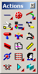
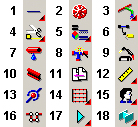
Actions Toolbar
|
The AutoSPRINK Actions toolbar has buttons for various "action" commands that can be performed on selected elements. Certain actions are applicable to any element, while others can only be performed on certain kinds of elements. In the Simple Interface, the Actions toolbar has seven extension fly-out buttons which gives more tool options. These tool options are available on other toolbars. To view the different tool options available on the extension fly-out buttons, click on the red fly-out arrow and hold down with the mouse. A tool can be selected by dragging the mouse to the desired tool and letting go.
|
|
|
1. Drawing - This is the first extension fly-out button on the Actions toolbar. These tools are the first 12 drawing tools available on the Tools toolbar. (Available in the Standard Interface.)
2. Sprinkler - Equips cursor with the sprinkler tool. Draws a sprinkler at a location you specify.
3. Auto Draw - This extension fly-out button extends to display most of the tools on the Auto Draw toolbar.
4. This extension fly-out button is comprised of the Trim/Extend tool, Scale Selection tool, Array tool, Rotate Selection tool, Group the Selection tool, Split All tool, Mirror tool, and the Divide Command tool. These tools are also on the Actions toolbar in the Standard Interface.
5. This extension fly-out button is comprised of the Match Color tool, Match Properties tool, Properties tool, Match Line Weight tool, Match Elevation tool, and the Match Layer tool. These tools are also on the Actions toolbar in the Standard Interface.
6. Get Defaults from Selection - Changes default properties for an element type to match those of the selected element.
|
7. Toggle Show Leaks - Turns visual indication of leaks in your system on or off.
8. Harmonize Selected Pipes & Fittings - Compares pipes and fittings and makes adjustments to fittings as needed so that they match pipes.
9. Cleanup Intersections - Breaks up intersecting elements into pieces at the point where they intersect, and fuse overlapping collinear elements into a single element.
10. Continuous Beam - Equips cursor with the beam tool. Draws a continuous line of adjacent beam segments, with each segment after the first having its starting point at the endpoint of the previous segment. Each beam segment remains individually selectable after the continuous line is drawn, and has its own individual properties.
11. External Reference - Opens a dialog box for selection of an external drawing file to reference, then equips the cursor to place that drawing in the current drawing as a symbol.
12. This extension fly-out button is comprised of the Ruler, Rounding, and Visible Grid tools.
|
13. Maintain Connections - When active, maintains connections between walls and beams, so that when a wall or beam is moved, connected walls or beams will stay connected, and will stretch.
14. Wizards - This extension fly-out extends to display the tools on the Wizards toolbar.
15. This extension fly-out button extends to display First Person, Auto Clip and Window Clipping Plane.
16. Arm Around - Opens the Arm Around dialog box if there is a conflict between objects such as pipes interfering with beams, or pipes interfering with columns. To view more information about the Arm Around tool, click on the left image.
Note: This tool button is also on the Standard Interface Auto Draw toolbar and brings up the Route Pipes dialog box.
17. This extension fly-out button is comprised of the Clip Planes tools.
18. This extension fly-out button is comprised of the Modeling tools.
|
|
Snap Tools
The Snaps Toolbar contains various tools and functions that enable snapping and rounding capabilities. AutoSPRINK elements such as walls, pipes and sprinklers are located, placed or joined to other elements using specific snapping tools such as the center snap, which enables the placement or joining of elements to a center location of another element. Snap Tool functions, from left to light of the Toolbar, are listed below.
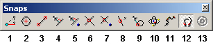
1. Ortho Snap - Enables you to draw tines and snap to points in 45-degree increments from the benchmark.
2. Center Snap - Enables you to snap to the precise center location of pipes lines walls, etc.
3. End Point Snap - Enables you to snap to the end location of any object.
4. Perpendicular Snap - Enables you to snap to the perpendicular of any object.
5. 3D Perpendicular Snap - Provides for a true 3D perpendicular snap between points in space.
6. Intersect Snap - Enables you to snap to intersection point of all elements in 2-D view.
7. 3D Intersect Snap - Provides for Intersection snaps between elements in 3D space.
|
8. Near Snap - Enables you to snap to any point along the nearest object. If you're near it, it will snap!
9. Tangent Snap - When active, snaps mouse cursor to a point touching (but not crossing) an existing circle or curve.
10. Special Element Snap - Enables snapping functions for pipe and wall elements only. Pipes will only snap to other pipes and walls will snap to other walls. This function speeds the design process when snapping pipes, fittings, sprinklers and walls near elements with different properties.
11. Snap into Symbol - When active, snaps mouse cursor to items grouped in a symbol.
12. Snaps Activation Tool - Activates/deactivates use of snaps that search for elements.
13. Enable AutoCAD Element Snaps - When active, snaps mouse cursor to items in an AutoCAD background.
|
|
Location Input Window
The Location Input Window enables users to numerically reference starting and location paints for object lengths and other design elements. With use of numeric input and the Location Input Window, users can plot the coordinates, location, elevation and placement of any AutoSPRINK element.
|

|
|
To relocate existing AutoSPRINK elements using the Location Input Window, simply
select desired element(s) and type in X, Y, Z coordinates with comma separating
each direction. In the illustration above, a selected element will be moved in the
Z direction (elevation) negative five feet. The numeric input displayed in the Location
Input Window above, consisting of two commas followed by a negative five, states
zero in the X and Y directions and negative five feet in the Z direction. (See X,
Y, Z, coordinates and numeric input in Section 2, Basic CAD Operations, for more
details regarding the Location Input Window and numeric input.)
|
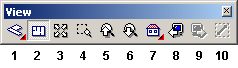
View Toolbar
The View Tools, located below the drawing screen, contain a secondary
set of Viewing Tools. Ten of the most commonly used viewing tools, also found in
the View Rotator, and are conveniently located for quick and easy access. View tools
from left to right include:
|
|
|
1. Isometric Views - This is the first extension fly-out button on the View toolbar. It is comprised of Isometric SW (southwest) View, Isometric SE (southeast) View, Isometric NW (northwest) View, and Isometric NE (northeast) View. Isometric views set the view to above a drawing and towards the specific directional (southwest, southeast, northwest, northeast) corner. All three drawing axes are scaled equally.
2. Top View - Sets the view to directly above your drawing, with the view direction parallel to the Z-axis of the drawing. (This is also known as plan view.)
3. Zoom All - Changes zoom level so all elements in the drawing are visible in the drawing window
4. Zoom Camera to Area - Zooms in on an area you select so that area fills the drawing window.
5. Zoom In - Zooms in one zoom increment. (Hold down the [Shift] key for a smaller zoom increment.)
|
6. Zoom Out - Zooms out one zoom increment. (Hold down the [Shift] key for a smaller zoom increment.)
7. This is the second fly-out button on the View toolbar. It is comprised of Left Side View, Front View, Right Side View, and Back View.
8. Previous Camera Position - Restores the view to the camera position immediately preceding the current camera position.
9. Next Camera Position - Restores the view to the camera position immediately after the current camera position. (Note - This button is not available unless the Previous Camera Position button has been used.)
10. Zoom Camera to Selection - Sets zoom level so that the currently selected element(s) fill the drawing window.
|
|
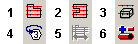
Hydraulics Toolbar

|
The AutoSPRINK Auto Draw toolbar has buttons for various commands found on the Auto Draw menu. These include the following in the Simple Interface for Platinum license users:
|
|
|
1. Remote Area - equips the cursor to maneuver an area of user defined square footage over a sprinkler system thus revealing the pressure, density and demand of the system within that area.
2. Remote Area Boundary - defines the remote area with a series of mouse clicks in 2-D.
3. Remote Area Box - define the remote area with a series of mouse clicks in 3-D.
|
4. Update Node Tags - Automatically generates and places node tags at all appropriate locations in the drawing.
5. Auto Peak -Searches along the branch lines contained within the selected remote area to find the most demanding area.
6. Hydraulic Analysis Reports - Graphically display the hydraulic information of the currently selected remote area in the drawing.
|
|
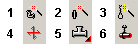
Auto Draw Toolbar

|
The AutoSPRINK Auto Draw toolbar has buttons for various commands found on the Auto Draw menu. These include the following in the Simple Interface for Platinum license users:
|
|
|
1. Auto Fittings - Automatically draws fittings for elements using parameters you specify. Can harmonize pipes and fittings if desired, and can replace incorrect fittings with correct fittings.
2. Auto Couplings - Automatically draws couplings between elements using parameters you specify.
3. Auto Hangers - Automatically draws hangers on selected pipes using parameters you specify.
|
4. Sway Brace - Equips cursor with the sway brace tool. Places a sway brace at a specified location.
5. Fittings - This extension fly-out is comprised of the tools on the Fittings toolbar. Click on the left image to view the Fittings toolbar.
6. Hanger - Equips cursor with the Hanger tool. Draws a hanger at a location you specify.
|
|
Select Toolbar

|
The AutoSPRINK Select toolbar has buttons for various selection and selection-related commands. These include the following for Platinum license users (Simple Interface):
|
|
|
1. Alter Benchmark Elevation/Rotation - Opens a dialog allowing you to set the elevation and rotation of the benchmark to values you specify.
2. Move Camera to Benchmark - In normal mode, points the camera at the benchmark so that the benchmark is in the center of the view. In First Person mode, moves the camera to the current location of the benchmark.
3. Move Benchmark - Equips your cursor with the benchmark tool, allowing you to move the benchmark to a location you specify.
4. Crossing Line - Equips cursor with line tool, allowing you to select any elements touching the line.
5. Crossing Window - Equips cursor with rectangle tool, allowing you to select any elements with one or more grips located inside the rectangle.
|
6. Alt-Window - Equips cursor with rectangle tool, allowing you to select any elements with any grips inside the rectangle. Grips outside the rectangle remain anchored in place, allowing selected elements to be stretched from anchored grips.
7. Toggle Ctrl - When active, AutoSPRINK will behave as if the [Ctrl] key is always pressed.
8. Z Lock - When active, forces drawing or dragging along your drawing's Z-axis. (Not usable in plan view.)
9. Select Last - Selects the most recently previously selected element.
|
|
|
AutoSPRINK Screen Layout
|
|
|
|
Main Toolbar
|
|
Menu ToolBar
|
|
Title Bar
|
|
Select Tools
|
|
|
|
|
Note: The install process may place AutoSPRINK's various tool bars at different
locations on your screen. You may, of course, dock these toolbars at similar locations
or place according to your own preference. The recommended screen resolution for
use with the AutoSPRINK CAD system is 1024 x 768, which allows for a sufficient
drawing area and enough space to include all available tool bars. To activate tools,
select 'Tool Bars' from the View Menu and activate by clicking desired Tool Bars
from the fly-out menu.
The AutoSPRINK CAD system was designed for the Windows operating
systems. Its strict adherence to Microsoft design standards and Windows conventions
provide for a state-of-the-art 3-D interface with smart objects, powerful tools,
commands and operations.
|
Back To Training Menu
|
|
|