|
|
|
AutoSPRINK Training Site - Adding Pipe to Database
|
From the ‘Parts Database’ menu, select ‘Add New / Edit Parts Book Pipe Type’, and
select the: “Create a new pipe type from scratch” option.
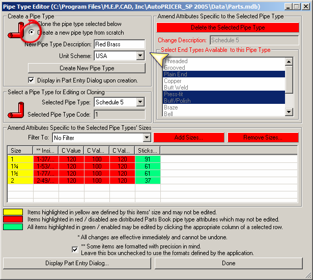
 Add a “New Pipe Type Description” and select the desired “Unit Scheme”. The ‘Display
in Part Entry Dialog upon creation’ option is selected by default and should be
deselected.
Add a “New Pipe Type Description” and select the desired “Unit Scheme”. The ‘Display
in Part Entry Dialog upon creation’ option is selected by default and should be
deselected.
Click on the ‘Create New Pipe Type’ button. Select the desired sizes
All sizes should be included, as sizes cannot be added at a later date – without
creating a new pipe type. (Internal Diameters are not editable once a pipe is created.)
Click ‘OK’
Select all End Types available to this Pipe Type. Adjust the data cell information
for “Inside Diameter”, “C Values” and “Sticks / Bundle”. Use decimal values for
US sizes. The value will be reflected in the current ‘Format’ set for ‘Diameters’
when the data is actually saved to the database. (Clicking on another data cell
saves the data. Be sure to do this for the last entry before continuing.)
Click on the ‘Display Part Entry Dialog’ button.

In Step 1: Select the ‘Create a New Part
from Scratch’ option, select “Pipe” as the
‘Category’ and find and select the new pipe
type (at the bottom) of the ‘Sub-Category’
list. The ‘Sub-Type’ should remain
“Standard”. A ‘Short Description’ can be
added, but usually isn’t used with pipe.
The ‘Is length Quantity…’ option needs to
remain selected for pipe.
In Step 2: Select, or type in, a
‘Manufactured By’ name (do not use
“Generic”). Select a ‘Color’ for the pipe and
set a ‘New Stick Length’
Step 3: Sizes are already included.
In Step 4: Click on the ‘Create Part’ button.

Any data “color-coded” in Green can be edited. Verify the ‘Finish’ information and
change whatever data needs to be edited. All data, on all tabs, for all sizes should be
complete and correct before continuing.
Click on ‘Done’ to close all dialog boxes when finished.
Note: When adding a pipe, default equivalent lengths for fittings must be added/verified.
This is done by clicking on "Edit Default Equivalent Lengths.."
button, from ‘Settings \Hydraulic Calculations \Fittings’ tab, and scrolling to the newly
created pipe type. These values would either be as shown on the Manufacturer’s data
sheets for the appropriate fittings use not the new pipe or the “Industry Standard…” as
recommended in NFPA 13.
Make sure that the equivalent length table option "Apply adjustments for Schedule 40
diameter and HWC 120 differences." is selected for the new pipe type. This option would
not apply for plastic or copper pipes where the equivalent length values are entered into
this table, using the Manufacturer's equivalent length data sheets, for which these
adjustments are already included in the values.

Back to Training Menu
|
|
|