|
|
|
AutoSPRINK Training Site - Complex Symbol Representation
|
Best way to start is to put a part in the drawing that you are going to want to make a complex symbol for…valve, strainer, etc.
When using a complex symbol, we do not draw anything. All is left up to the symbol. That’s why you should use the existing fitting as a template
to get the connection points in the right spot.
Place AutoSPRINK fitting (as similar as possible to what you want) and edit size and takeouts if necessary, make sure you just drop one in that doesn’t have a rotation.

Draw all you want around the fitting.
Create the complex shape and make it a symbol or import 3ds model, dwg, etc. (either way, it must be made a symbol, with the benchmark at desired insertion point)
The Benchmark has to be at the same location as the fitting center point when making the symbol. To make the object a symbol eirther Right click and select Create Symbol or go to the Menu bar and select Actions then select Create Symbol

Select symbol and part (order doesn’t matter) and then go to the Menu bar and select Commands then Complex Symbols then Create

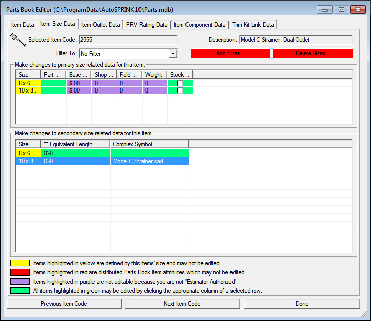
To view where the Complex symbol is being referenced, Edit your part using the Parts Database Menu and selecting Edit Part in Database or Selected Part. Then
go to the Item Size Data Tab
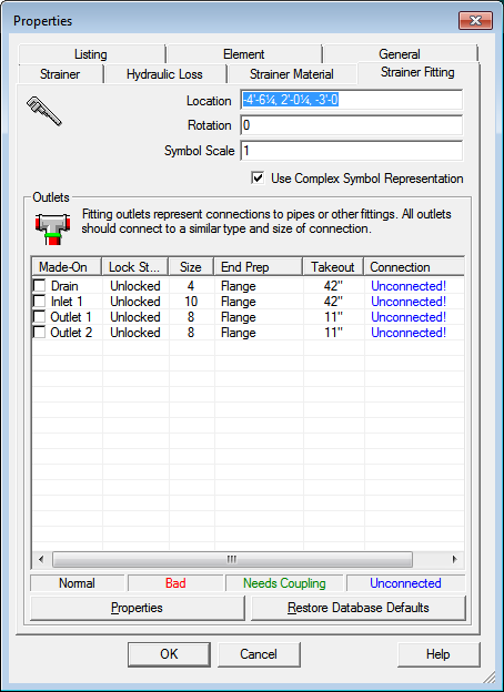
You may also shut off the display of the Complex Symbol and turn back on the original symbol. Go into the properties of the Complex Symbol, and as you can see it currently should be checked to display the Complex Symbol.
A symbol needs to be made for each size.
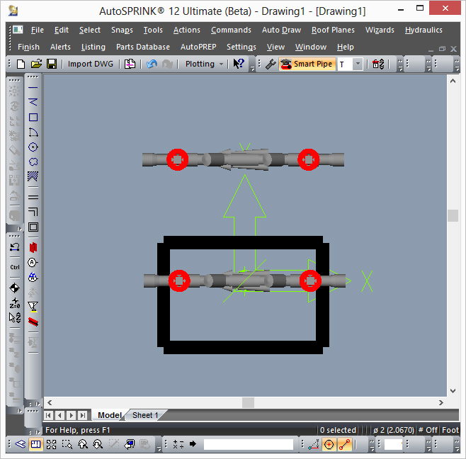
The symbol will rotate with the fitting and really is the fitting. The program just draws the symbol instead of what would normally be drawn, if the symbol exists. Picture:

Hydraulically, in this example of a new Strainer, it does flow out of both outlets and reports it’s node at the center of the fitting.
Back to Training Menu
|
|
|