![]()
The Connect Appliances to Circuit command, for those who rely on the Manual Connection mode when connecting alarm systems, links selected appliances to available panels with a circuit.
To Connect Appliances to a Circuit, highlight the target appliance(s) and click either the Connect Appliances icon on the Circuit toolbar, or choose Connect Appliances to Circuit from the Commands menu. Alternatively, highlight the target appliance(s), right-mouse click, and the Connect Appliances to Circuit command is available within the pop-up menu.
Please Note: If no sources with available circuits to support the target appliance are available, a warning will appear in the drawing. In addition, a warning will appear if no unassigned appliance circuits are available in the selected set. Target appliances must have a wire path connection to a source for the command to function.
 Once the
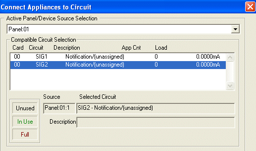
Connect Appliances to Circuit dialog
appears, choose an active panel from the Active
Panel/Device Source Selection drop-down menu.
The chosen panelís circuits appear in the Compatible Circuit Selection list dialog.
Choose the desired connection circuit from the list; the column headers separate the compatible circuits by Card Number, Circuit Number, Description, Appliance Count, and Load (in mA).
![]() Please Note:
Please Note:
Unused circuits in the list will appear in plain black text; circuits in use will appear in green; full circuits will appear in red.
In addition, to quickly view the highlighted circuit in the list, its brief description appears in the Source, Selected Circuit, and Description fields.
 The selected
appliance and any others that precede it on a shared wirepath
are listed in the Appliance Selection
list dialog box.
Check or uncheck an appliance to be included in or excluded from the connection process with a single, left-click on its row. To expedite the selection process, click All or None to include or exclude all appliances in the list.
To help users differentiate the Target Appliance(s) in the list (especially in cases with identical appliances), they will be checked with a blue "X" in the list dialog, as indicated in the image above. The number in parentheses, (1) in this case, indicates the Required Circuit Number of the device being connected.
![]() Please Note: Targeting
additional appliances will simultaneously highlight them in the drawing.
Please Note: Targeting
additional appliances will simultaneously highlight them in the drawing.
.gif) Under
the Connection
dialog, selecting the Generate
Circuit in Cables option causes the circuit to automatically generate
in existing cables.
Under
the Connection
dialog, selecting the Generate
Circuit in Cables option causes the circuit to automatically generate
in existing cables.
Under the Wiring section, choose Allow Branching to allow the T-Tapping of wirepaths or No Branching to exclude the wirepaths from being T-Tapped. The diagrams on the left illustrate both wiring types.
When the connection variables are modified as desired, click the OK button to save the work, and the appliances will connect to a circuit.
Clicking the Cancel button will exit the command without saving the work.
To ensure the circuit connection was completed, double-click on the wire path in the drawing, and its Properties page appears. The circuit should be listed under the alarm wire path's main Properties page.
To view the newly-added circuit's Properties page, double-click the circuit's row.
To learn more about the Circuit Properties page, click here.
Design Standards Guidelines Tab: Auto vs Manual Mode