![]()
 When adding a new appliance
to the Parts Database, use the Required
Circuits page (tab) to designate essential circuits that must be
in place for the device to operate.
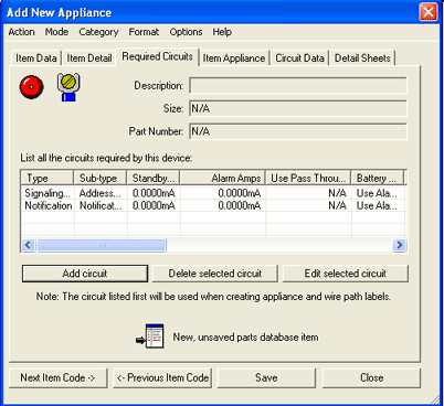
The middle list control table will display the device's required circuits, categorized by type, sub-type, standby and alarm amperage, pass-through current usage, battery and voltage data. For a complete list of connection information, see the Connection Information dialog below.
Use the horizontal scroll bar at the base of the window on the Required Circuits Page to examine columns of circuit characteristics not currently visible.
To learn how to add required circuits to an appliance, proceed to the Add Required Circuits section below.
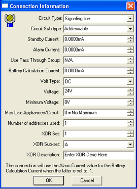
Add circuits required by the device to the list dialog box by clicking the Add Circuit button. After the Connection Information dialog appears (image below left), choose the desired circuit type, subtype, current, voltage, and addressing properties from the available drop-downs and fields. Users can add similar circuit types and subtypes multiple times into the list control table.
![]() Please Note:
Please Note:
 Note the available value of '-1'
for Circuit Type and Subtype in the top two drop-down menus (left image).
This value is available for appliances that can connect to multiple circuit
types and/or subtypes. Assigning the '-1'
value allows the appliance to connect to ANY
circuit type and/or subtype.
 AlarmCAD for AutoCAD-specific
optional circuits, known as XOR Sets,
Subsets, and Descriptions,
will further define the device's list of required circuits. Please note
that 'XOR' circuits are specific to AlarmCAD for AutoCAD software. Required
circuits may change since many AlarmCAD for AutoCAD devices require multiple
circuits to connect properly to fire alarm control panels and other sources.
For more information on XOR Circuits,
click here.
The XOR Set description defaults to N/A, but users can customize its description with any number.
XOR Subset defaults to 'A,' but any letter in the alphabet can be used to describe the Subset.
The XOR Description field is customizable as well.
Click OK to place the new information in the main Required Circuits Page. Alternatively, click Cancel to close the dialog and exit without saving.
To make modifications to a circuit, highlight its row from the main Required Circuits page (top image above), and click Edit Selected Circuit button to pull up the Connection Information dialog again. Alternatively, double-click the circuit's row to bring up the Connection Information dialog again.
The Delete Selected Circuit button will remove the highlighted circuit from the list.
When all necessary circuits appear correctly in the main list control table, click the Save button. Move on to the Item Appliance tab, or click Close to end the process and return to the drawing field.