![]()
To go directly to the XOR Supply Circuit information, click here.
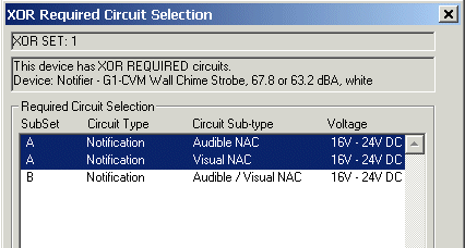
Many devices in AlarmCAD for AutoCAD require multiple circuits to connect properly to fire alarm control panels and other sources. Depending on the intended use of the device, its list of required circuits can change. These circuit sets are specified through AlarmCAD for AutoCAD's XOR Sets and Subsets. Users will be prompted with the XOR Required Circuit Selection dialog (image below) only if the device requires XOR Sets and Subsets.
XOR sets and subsets are listed within a device's Appliance Page in the first Circuits Required by Device dialog box. If devices do not require XOR Sets and Subsets, they will not appear.
 As mentioned, the dialog on
the left will only appear if the device requires an XOR
Set/Subset.
For example, a Relay Device can connect to several different circuit types and subtypes. Users can choose which XOR Sets and Subsets to use prior to connecting the device to its source and wire path.
Only one Subset can be selected at a time (at left, either Subset A or B). By design, multiple-circuit Subsets cannot be selected simultaneously.
The device's Appliance Page contains a Circuits Required dialog box that allows users to view which circuits are connected and disconnected.
Pressing the XOR Reset button on the lower right side of the Circuits Required dialog box causes the above XOR Required Circuit Selection dialog to reappear. However, if XOR circuits are already assigned, the XOR Reset button will be disabled.
Once the device is connected to its source and required circuits are defined, the XOR Set Selections can no longer be modified. However, if the device is later disconnected from its source and wire path, XOR set selections can be modified once again.
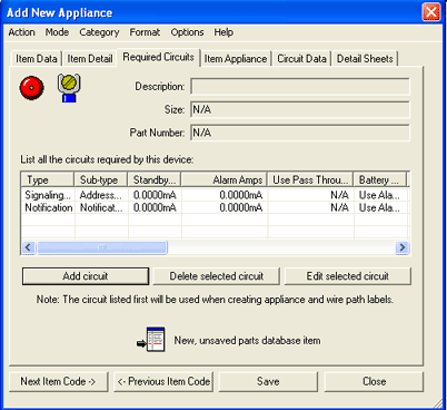
 When adding or modifying an
existing appliance (Accessed via Parts
Database Menu), XOR Set and Subset information is found within the
Required
Circuits Page. For
additional information on the Required Circuits Page, follow the link
above.
Please Note: Default Values for XOR Sets display as N/A, which indicates that the XOR sets should always be included on the device.
Multiple XOR Sets can be added as needed, so users will be prompted to identify an XOR Subset to use for each defined XOR Set.
1. When Required Circuits should always be included on a device, the XOR Set should remain as N/A.
2. When only one of several Required Circuits is to be included on a device, assign the same XOR Set to all the circuits, but assign different Subsets. (e.g. From five available choices, assign easily-distinguishable Subsets such as A, B, C, D, and E.)
3. Please note that the XOR Set and XOR Subset values do not have to be in any specific order.
Similar to the XOR Required Circuits, the list of supply circuits associated with a source card can change. However, XOR Subsets are not used to further define Supply Circuits.
 When placing a Source Device
that contains XOR Sets in one of its panel
cards, the dialog on
the left appears, which allows the user to choose the XOR Set to include
in the source. By
design, only one XOR Set can be selected at a time. Like
the XOR Required Circuits, users will be prompted to define each XOR Set
only if the device requires XOR circuits.
As long as a source's circuit is not connected, XOR Set selections are modifiable. The XOR circuit information will be displayed in the Appliance Tab/Circuits Provided dialog box. Pressing the XOR Reset button on the lower right of the dialog box will allow users to make modifications within the XOR Source Circuit Selection dialog.
Once the Source's circuit is in use, the XOR Set Selections can no longer be modified. If the device is later disconnected, however, XOR Set selections can be edited again.
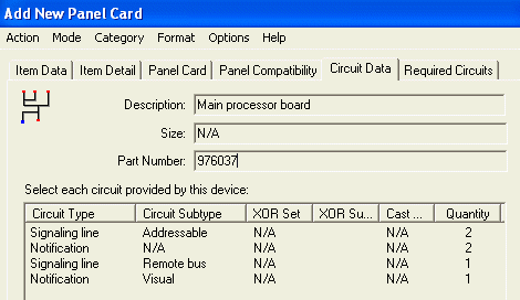
 When entering or modifying
a source device within the Parts Database, the Circuit Data Page will
allow users to define XOR Set information on the device's provided circuits.
The image on the left displays the Circuit
Data Page for a processor board.
1. Default Values for XOR Sets will display as N/A. If Supply Circuits should always be included on a source card, the XOR Set should be defined as N/A.
2. Just as in the XOR Required Circuits, the XOR Set values for Supply Circuits do not have to be in any specific order.