![]()
 Depending on the type of Fire
Control Panel or Auxiliary Panel used, it may be comprised of several
Cards (formerly known as nodes). An individual Card may require several
circuits to operate, and/or may supply numerous circuits to the Panel.
Depending on the type of Fire
Control Panel or Auxiliary Panel used, it may be comprised of several
Cards (formerly known as nodes). An individual Card may require several
circuits to operate, and/or may supply numerous circuits to the Panel.
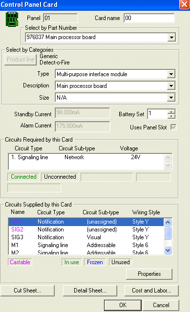
From the Auxiliary Panel's Properties Page or the Fire Control Panel's Properties Page, the Cards in this Device dialog box displays the number of Cards and the number of Circuits and Battery Sets comprising the Cards. The large image on the right show the Control Panel Card's Properties page. Several dialog boxes are found in the Control Panel Card's Properties page, so each will be explained in more detail below.
This page may look familiar, as a Device's Appliance Tab displays a cumulative list of all circuits comprising all cards within the device. This page allows users to view individual circuit's properties contained within one Panel's card.
The first Card from the above dialog box was chosen from a generic product line, Part Number 976037, the Main Processor Board. The Product Line button may be available for those who use multiple manufacturers' products. Users can modify the Card's Part Number or Type, and where applicable, its Description and Size.
Once users choose the Part Number/Type of panel card, the Standby Current and Alarm Current fields auto-populate with a Parts Database-defined value. The Current values in the fields are for the user's reference and not editable, since this information is gathered from the Parts Database.
Users need to employ their own experience and judgment when assigning the number of battery sets allocated to each card. The Battery Set number defaults to one, but is adjustable up to ten.
The Uses Panel Slot option box is defined from the Parts Database, and is checked/unchecked for the user's reference only. Like the Standby and Alarm Current fields, this option box is for the user's reference.
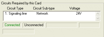 Circuits Required by this Card
Like the Appliance Tab's Circuits Required dialog box, individual Required Circuits can be viewed. If applicable, some circuits can be modified if they weren't previously classified in the Parts Database. In the example image to the right, both the Circuit Type and Circuit Sub-type have already been assigned, so cannot be further modified from this dialog. Each Circuit's connection status is listed either in black (Unconnected) or green (Connected).
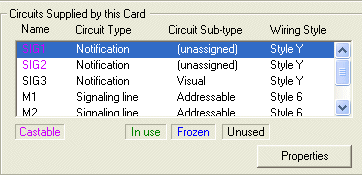 Circuits Supplied by this Card
Like the Appliance Tab's Circuits Provided dialog box, individual Supplied Circuits can also be viewed.
If applicable, some circuits can be modified if they were not previously classified in the Parts Database. In the example image on the right, Sig 1 and Sig 2's circuit Subtypes have not yet been assigned, so the Properties box appears at the bottom right.
Each circuit's status is identified by color: pink (castable), green (in use), blue (frozen), and black (unused).
For more information about the Circuit Properties Page, click on the image.
For more information about .Castable Circuits, click here.
Click the Cut Sheet button to open an Adobe .pdf file with the manufacturer's specs.
The Detail Sheet button will direct users to the manufacturer's website, intranet, etc. and display the installation Detail sheet drawing, if it is available for the part.
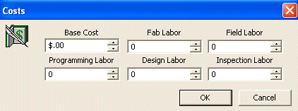 The
Cost and Labor button will reveal
a Costs dialog on the right. Users can enter the circuit's Base Cost,
Fabrication Labor, Field Labor, Inspection Labor Hours etc. for the circuit.
These amounts
will be picked up during reporting, such as in the Bill of Material, Inspection
Labor Report, etc.
The
Cost and Labor button will reveal
a Costs dialog on the right. Users can enter the circuit's Base Cost,
Fabrication Labor, Field Labor, Inspection Labor Hours etc. for the circuit.
These amounts
will be picked up during reporting, such as in the Bill of Material, Inspection
Labor Report, etc.
Parts Database: Circuit Data Tab-Provided Circuits
Parts Database: Required Circuits Tab
![]()