![]()
AlarmCAD for AutoCAD appliances may require and/or provide certain combinations of circuit types/subtypes, wiring styles, and other properties in order to operate and connect with other appliances. The Define Circuit Data Cast Keys command allows users to define new, compatible circuit groups known as Cast Keys.
User-created Cast Key members can be used in the future when defining new appliances' properties (Cast Key column found in the Circuit Data page). The image below displays the Define Cast Keys dialog.

1.
To add a new Key to the Parts Database, click the Add
Key button. ![]()
AlarmCAD for AutoCAD will then generate a new Key number in the top left Key field. In the above image, the new number is 70900010. The Key number is derived from the software licensing key located in the back of the computer.
2. By default, AlarmCAD for AutoCAD generates a new Key Member in the first row of the table.
To modify this Key Member, click directly within a cell, and choose another item from the drop-down menu.
For those cells without drop-down menus, users can enter a value directly in the cell, as in the Max Appliances, Max Amps Circuit Branch Count, Terminal Voltage, and Max Capacitance columns.
3.
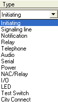
Depending on the Circuit
Type chosen for the Key Number (options
in left  image), the
subsequent cells (in the Circuit
Subtype and Wiring
Style columns) will offer the appropriate
choices from their drop-down menus. To avoid confusion, no extraneous
choices will appear in the other cells.
The Maximum Number of Appliances defaults to a -1 value, which means that no limit exists for the number of associated appliances. Users can insert a maximum number of appliances, if applicable.
Voltage Type offers several choices such as 'AD,' 'DC,' etc.
Voltage contains an editable field to be defined by the user.
Max Amps defaults to 'No Maximum,' but users can insert a value.
Terminal Voltage defaults to 'Use Voltage Value,' but users can insert another value.
Circuit Branch Count defaults to '0,' but users can insert another value.
Max Capacitance also defaults to '0,' but users can insert another value.
4.
Insert additional Key Members
that comprise the main Cast Key by clicking the Add
Key Member button. ![]()
Then, follow the same procedure as in steps #2 and #3.
1.
To remove a Cast Key, ensure the
correct Cast Key number populates the top left Key
field, then click the Delete Selected
Key button. ![]()
2. To remove a Key
Member from the table, ensure the correct Key Member is highlighted,
then click the Delete Selected Key Member
button. ![]()
To range-select multiple, non-consecutive Key Members in the list, use the [Ctrl] Key/left-click combination.
To range-select multiple, consecutive Key Members in the list, use the [Shift] Key/left-click combination.
Then, click the Delete Selected Key
Member button.![]()
![]() Please
Note: All changes made within this
dialog are effective immediately and cannot be undone. However, users
can close out of the dialog, then return to make modifications, additions,
and deletions.
Please
Note: All changes made within this
dialog are effective immediately and cannot be undone. However, users
can close out of the dialog, then return to make modifications, additions,
and deletions.