![]()
The Calculations tab allows users to adjust compensation factors and tolerances for Appliance Voltage, Cable Length calculations, and Battery Calculations. Because of the complexity of the Calculations Tab, each dialog box has been divided into three sub-topics and explained in detail below.
 Maximum Operating
Voltage Drop
Maximum Operating
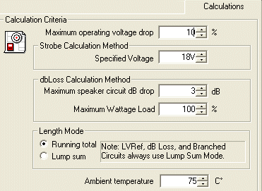
Voltage DropIf a circuit's voltage drop exceeds the designated percentage, an error message appears in the Circuit Properties page in the Circuit Information dialog box. This field defaults to a 10% maximum voltage drop, but is adjustable.
The specified voltage of 18V will appear by default, but is adjustable from 17V to 24V. When the specified voltage value is assigned in this field, it will be used for all strobe calculations for the drawing. AlarmCAD for AutoCAD's internal calculation method, though similar to the alarm's calculation method, differs slightly, so it will yield different results.
When the Strobe Calculation method is used, a notification appears for users in the Circuit Properties page/Circuit Information dialog box: Calculation method: Strobe. Based on calculated current values.
The Strobe's Calculation result will appear at the bottom right side of the Circuit's Properties page in the Circuit Calculations dialog box as the Total Current Load (in mA).
 When placing speakers in a series, the dBLoss Calculation method incorporates the user's defined Maximum
speaker circuit dB drop and Maximum
Wattage Load to complete the calculations.
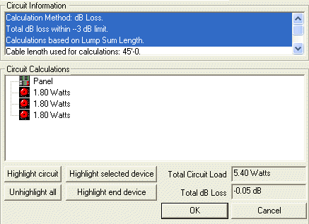
Like the strobe and alarm calculations, the dB Loss calculation notification appears within the Circuit's properties page in the Circuit Information dialog box, which is highlighted blue in the image on the left. The calculations results display on the bottom right side of the page (refer to image on left).
Please Note: dB Loss Calculations are ALWAYS based on the lump sum length mode (all devices are placed at maximum length). If the Length Mode Settings from the Design Standards/Calculations tab are set to Running Total, they will be ignored.
 By
default, the Running Total length
mode is selected, which considers distances between individual appliances.
The running total mode calculates the actual representation of total length,
but is not used for every type of calculation method. For the user's reference,
a note lists the types of calculations that always use the Lump
Sum mode: LVref
(Low Voltage System Reference), dB Loss, and Branched Circuits (see
Length Mode image to the left). The Lump Sum mode calculates all devices
at their maximum lengths, not actual lengths.
Users now have the ability to control the
temperature at which wire resistance is calculated. Ambient temperature
can be adjusted so calculations can be run at varying temperatures. By
default, the Ambient temperature is set to 75
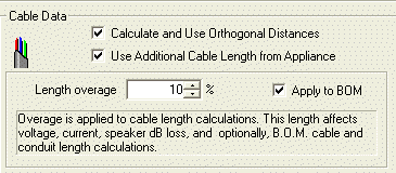
 Cable Data options are NOT
turned on by default. Not
checking any options will prompt the calculation to consider the actual
distances between appliances. Choosing
Calculate and Use Orthogonal Distances
will consider the orthogonal distance between each appliance. Checking
the last option, Use Additional Cable
Length from Appliance will consider any extra cable that any appliance
contains.
Please note that both of these options can be selected if desired, as is reflected in the image above. Cable length calculations will appear in the Circuits' default properties page at the bottom in the Length dialog box. Both options will take into account the user's defined Length overage percentage, which defaults to 10%, but is modifiable. From the Apply to BOM option box, users can control whether or not cable length overage is added into the Bill of Material (BOM) cable lengths.
 When calculating the supervisory
current load, the Battery Calculations dialog box contains user-definable
Standby and Alarm compensation factors.
Please Note: Some appliances, such as the Fire Control Panel and Auxiliary Panel, display Design Standards/Calculation Tab's compensation factors within their default properties pages. If future adjustments in compensation factors are needed, users can change them within the individual appliance's default properties page as well.
Introduction to Design Standards
Design Standards Guidelines Tab
Design Standards Bill of Material Tab
Design Standards Calculations Tab
Design Standards Appliance Labeling Tab