![]()
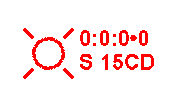
 Clicking the
Notification Appliance icon from the Alarm
Tools toolbar or Notification Appliance
from the Tools menu equips the
cursor to place bells, strobes (left image), horns or chimes (right image)
into the drawing field.
Notification appliances' symbols correspond with notification types: Lines surround strobes to denote their visibility, music notes symbolize chimes, triangles represent horns, and circles represent bells.
To access its Default Properties Page, double-click the Notification Appliance symbol in the drawing. Alternatively, right-click on the symbol and choose Properties from the pop-up menu.
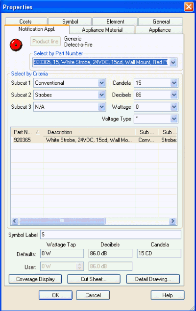 Default Properties Page
Users can select the notification appliance by its part number via the top drop-down menu. Notice how the Part Number corresponds to the choices made in the Select by Criteria section. Alternatively, filter the Sub-Category variables to locate the desired part.
Note also the Candela, Decibel, Wattage and Voltage type fields will correspond with the chosen part number. Some of these drop-down menus may not populate, depending on the type of notification appliance.
Modify the Symbol Label in the corresponding field below the middle list control table.
Appliances with wattage, decibel, or candela values will display toward the bottom of the main Properties Page.
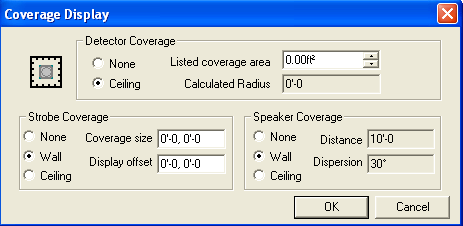 Users modify coverage area displays via the main Properties
Page. Once the Coverage
Display dialog appears on the left, users can edit the fields
as needed for the device. By default, each is set to 'None,' or no coverage
display. For emphasis, the left image shows an option enabled in each
section.
Click here to view an initiator's (detector's) coverage display.
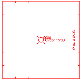
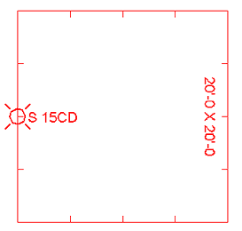 Strobe coverage areas offer three options: None, Wall,
or Ceiling.
Note how the strobe's wall coverage area displays in the left image when its coverage size is set to 20'-0,20'-0.
In the image above right, the strobe's ceiling coverage area displays as a rectangle surrounding the device.
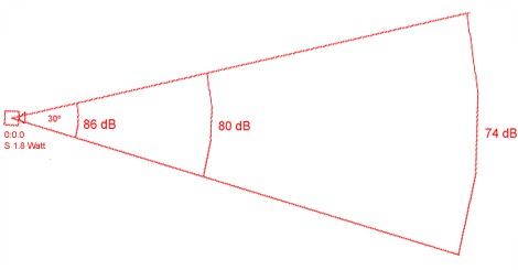 A Speaker's coverage
area display offers three options: None, Wall or Ceiling.
For those opting for wall coverage, the speaker's coverage distance and dispersion angle are automatically calculated.
In the left image, note how the decibel levels decrease with increasing distance from the speaker. The speaker's wall coverage area resembles a sector of a circle.
For ceiling coverage, multiple circles would surround the speaker with differing 'radii,' again illustrating decreasing decibel levels with increasing distance from the speaker. Imagine the above image displaying three complete circles, with three 'radii' at 86 dB, 80 dB, and 74 dB.
Click the Cut Sheet button to open an Adobe Reader .pdf file with the manufacturer's specs.
Click the Detail Drawing button to assign manufacturers' detail drawings to the device, if applicable.